Comfort 250 Top
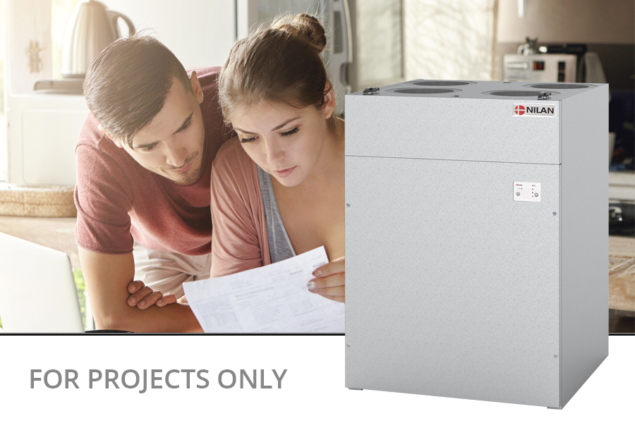
Comfort 250 Top is an energy-efficient ventilation unit with heat recovery designed for homes with a ventilation requirement of up to 250 m3/h. Comfort 250 Top is only available for project sales.
Comfort 250 Top is equipped with a unique boost function intended for cooker hood operation. Upon user activation, an additional 50 m3/h is provided to ensure proper suction in the cooker hood. Through the boost function, Comfort 250 Top can deliver 300 m3/h at 200 Pa external pressure loss.
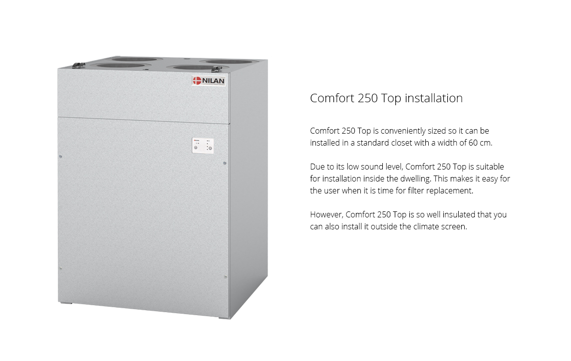
The unit is designed for top connection and has a very low noise level, allowing for indoor installation. Comfort 250 Top is a ventilation system with compact dimensions, enabling it to be installed in a 60 cm wide cabinet. The control panel is integrated into the front, eliminating the need for additional mounting. However, it is possible to detach the panel.
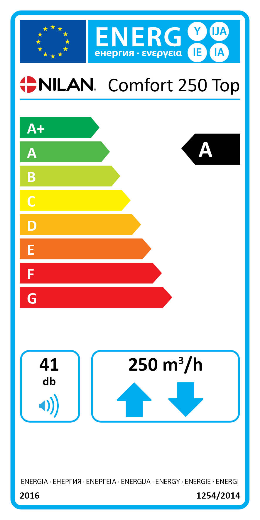
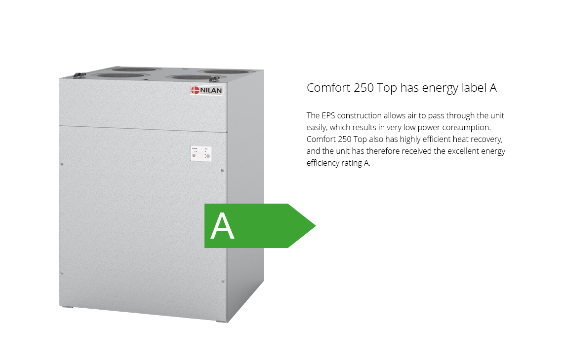
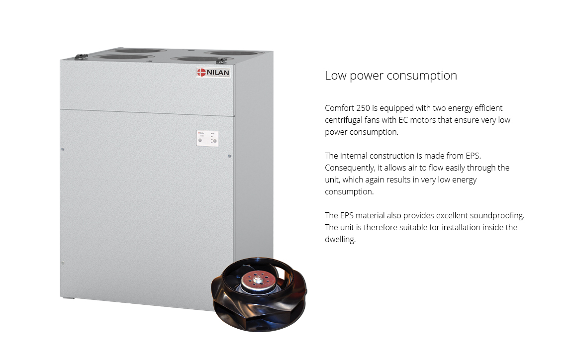
Comfort 250 Top is constructed to achieve low power consumption and high heat recovery. This combination results in an energy efficiency rating of A.
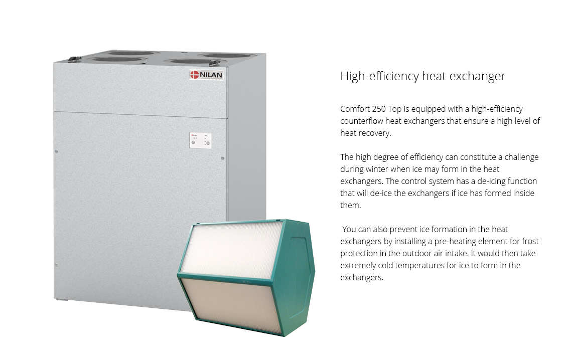
Comfort 250 Top is also available in a Polar version, which is equipped with a self-regulating preheating element. The preheating element protects the unit in cold outdoor temperatures by heating the supply air and preventing frost formation in the heat exchanger.
Airflow (see planning data for SEL/SFP values)
Min : 0 m3/hMax : 250 m3/h

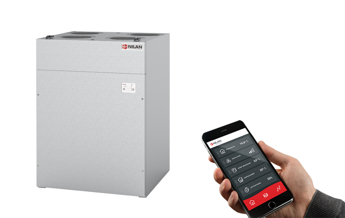
Nilan App - Control the ventilation and heat pump directly from the mobile phone
|
Nilan has developed an App with great features where the user can control the ventilation and heat pump directly from the mobile phone. The App is intuitive, easy and safe to use, and allows the user to e.g. set the room temperature. More ventilation units can be connected using the same App to control the indoor climate in e.g. both the dwelling and the holiday home. More users can be connected the same App. When purchasing a Nilan gateway, the user can access the unit via the Nilan App. Get more information on the Nilan App
|
 |
|
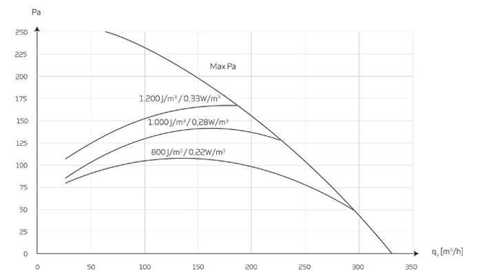
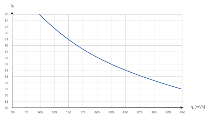
CapacityCapacity of standard unit as a function of qv and Pt ext SEL values according to EN 13141-7 are for standard units with ISO Coarse >75% (G4) filters and without heating element. SEL values represent the unit’s total power comsumption for both ventilator, excl. control. Testet according to EN13141-7 Attention! The SEL values are measured and stated as a total value for both fans. |
 |
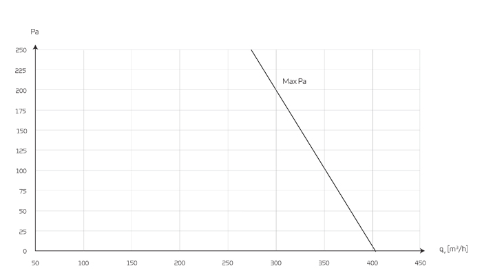
Capacity (boost function)The CTS400 has fan speed levels 5 and 6, both of which are connected with user selection 1 and 2. In this way, you can boost the air volume when eg. there is a cooker hood connected. |
 |
Temperature efficiencyTemperature efficiency for units with counterflow heat exchanger according to EN13141-7 (dry). |
 |
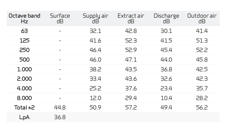
Sound dataSound data for qv = 126 m3/h and Pt ext = 100 Pa according to EN3744 for surfaces and EN 5136 for ducts. Sound output level LWA drops with falling air volume and falling back pressure. Sound pressure level LpA at a distance of 1 m from the system. |
 |
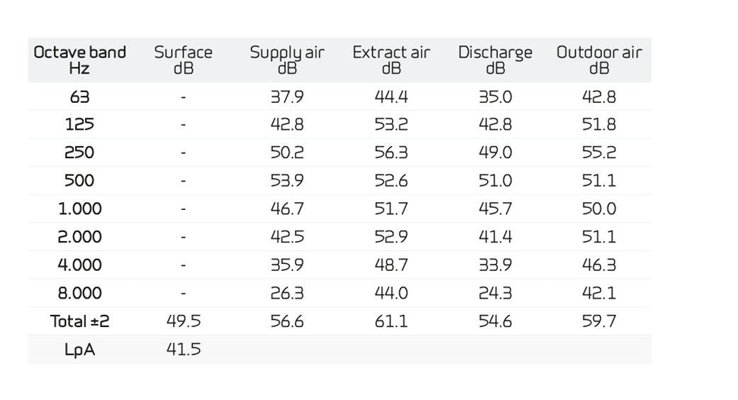
Sound dataSound data for qv = 250 m3/h and Pt ext = 100 Pa according to EN3744 for surfaces and EN 5136 for ducts. Sound output level LWA drops with falling air volume and falling back pressure. Sound pressure level LpA at a distance of 1 m from the system. |
 |
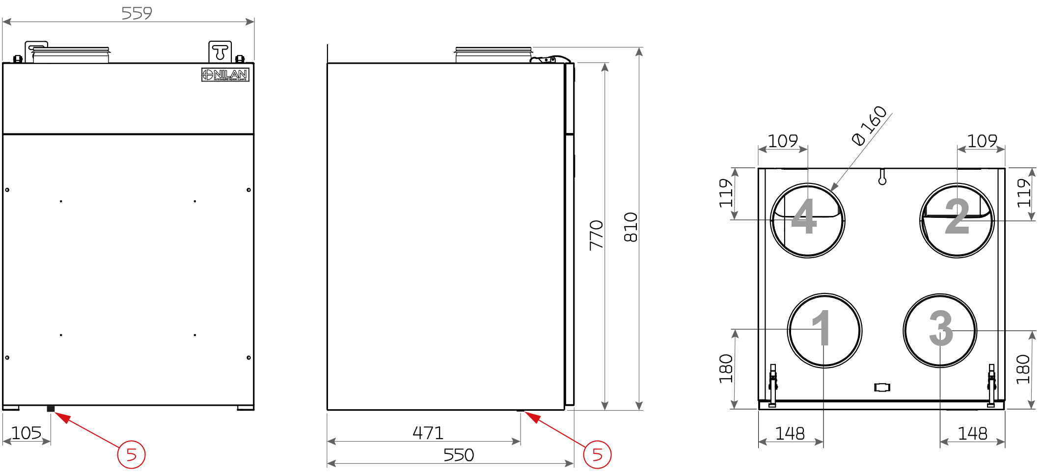
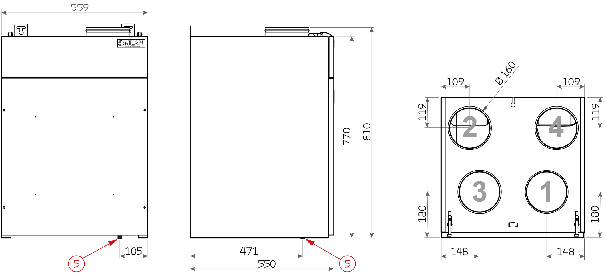
You can download AutoCad or Revit drawings with BIM data on several Nilan ventilation and heat pump solutions - the list is constantly being expanded. Click here to get more about BIM data on Nilan units Dimensional drawing Comfort 250 Top (Right version)
Dimensional drawing Comfort 250 Top (Left version)
All dimensions are in mm. Connections:
Dimensional drawing Comfort 250 Top Polar (Right version)
Dimensional drawing Comfort 350 Top Polar (Left version)
All dimensions are in mm. Connections: |


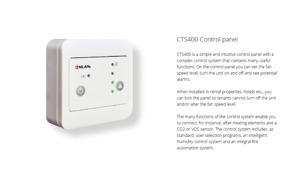
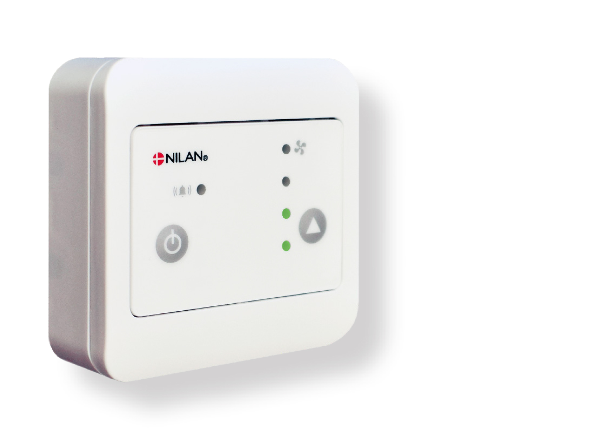
CTS400 is a simple and intuitive control panel with a complex control system that contains many useful functions. On the control panel you can set the fan speed level, turn the unit on and off and see potential alarms. When installed in rental properties, hotels etc., you can lock the panel so tenants cannot turn off the unit and/or alter the fan speed level. The many functions of the control system enable you to connect, for instance, after-heating elements and a CO2 or VOC sensor. The control system includes, as standard, user selection programs, an intelligent humidity control system and an integral fire automation system. CTS400 has open Modbus communication that enables connection to external CTS systems. The Modbus connection can also be connected to a Nilan gateway cloud solution that allows you to control and monitor the unit via a smartphone APP solution.
|
ATTENTION! When positioning the unit, you should always consider future services and maintenance. An open space of minimum 60 cm in front of the unit is recommended. It must be easy to change filters, and it must, for instance, be possible to remove the heat exchanger, and to replace fans or other components. ATTENTION! The unit must be level to enable proper drainage from the condensate tray. The unit is equipped with mounting brackets with holes for wall mounting at the top back of the unit.
|