VPL 28
VPL28 is a ventilation unit with heat recovery that is perfect for e.g. a small office, a small retail outlet or a practice that requires cooling. It differs from an ordinary ventilation unit by being equipped with a heat pump rather than the usual counterflow heat exchanger.
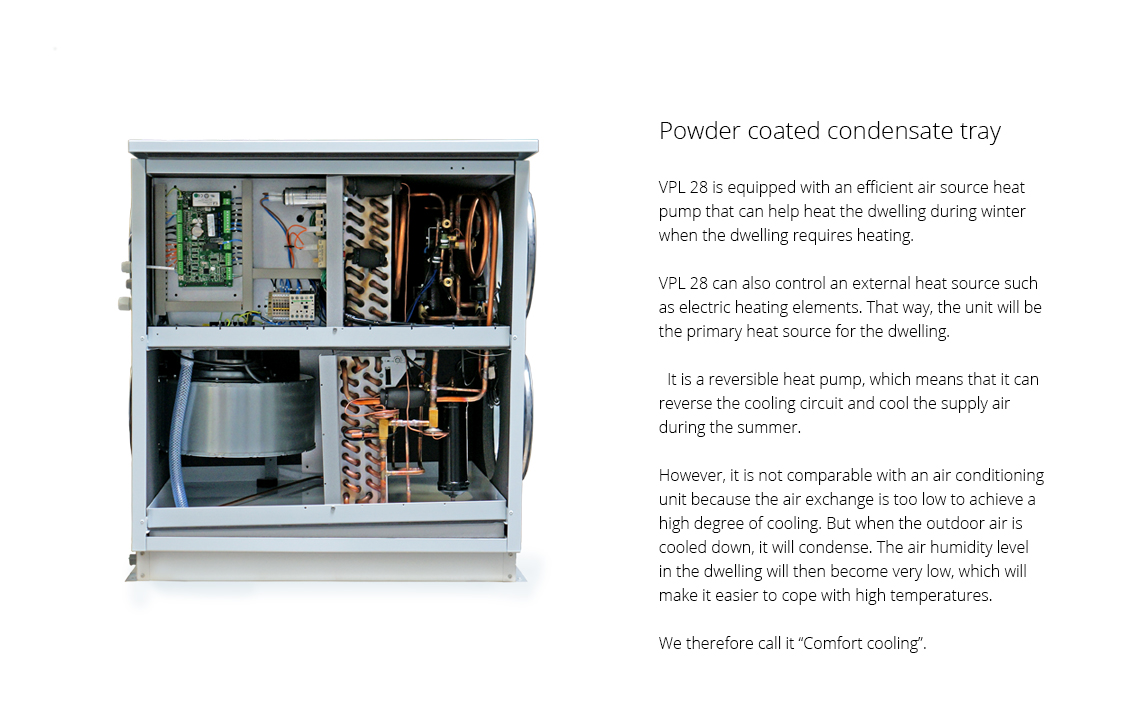
The heat pump enables you to achieve a higher level of heat recovery than traditional solutions. The VPL28 heat pump has a reversible cooling circuit, which means that it heats the supply air during winter and cools the supply air during summer as required.
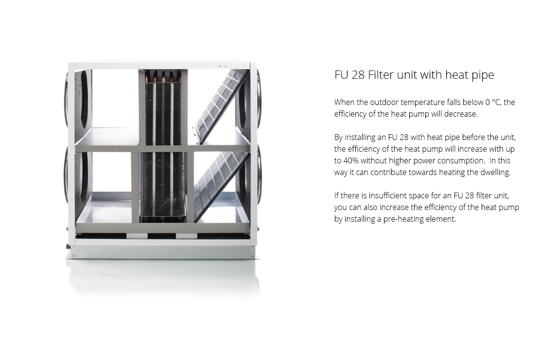
FU28
You can purchase a heat pipe for your VPL28. It increases the efficiency of the heat pump with up to 40% during the winter without higher power consumption.
Airflow (see planning data for SEL/SFP values)
Min : 400 m3/hMax : 1250 m3/h
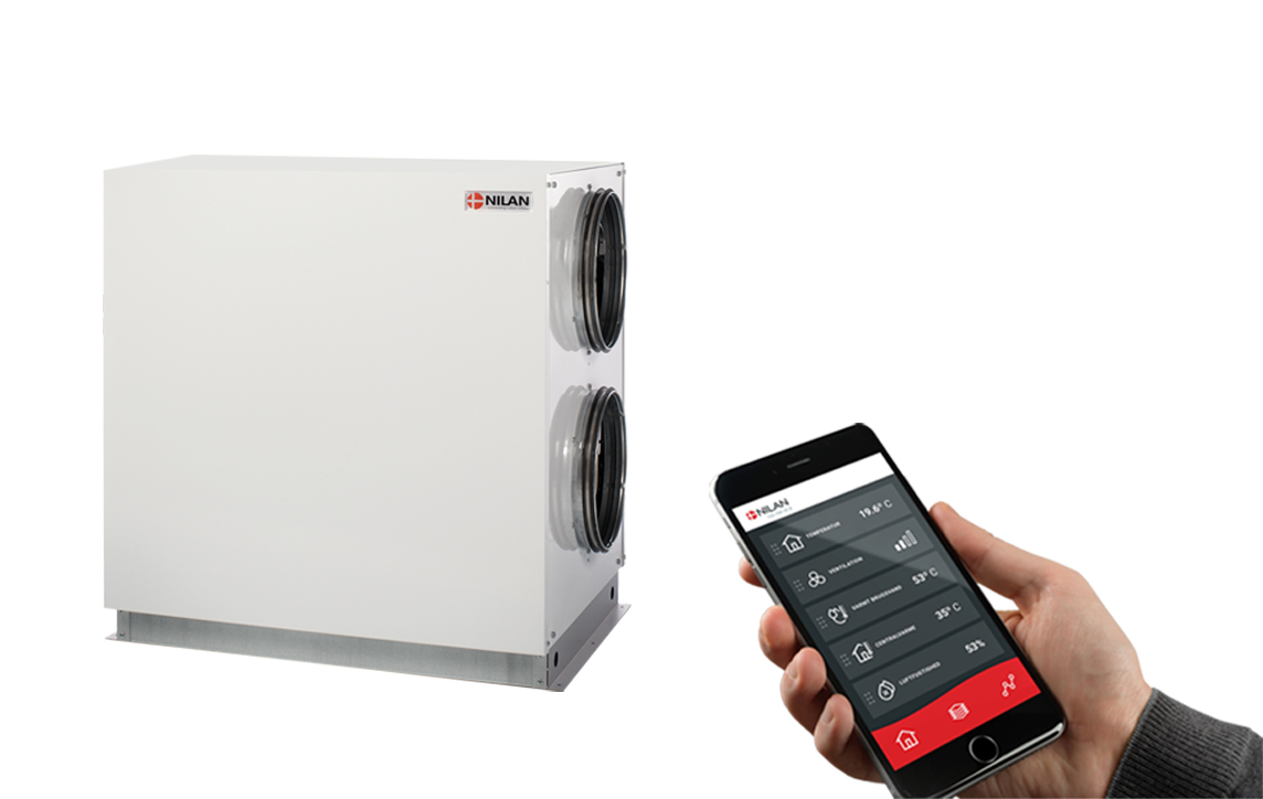
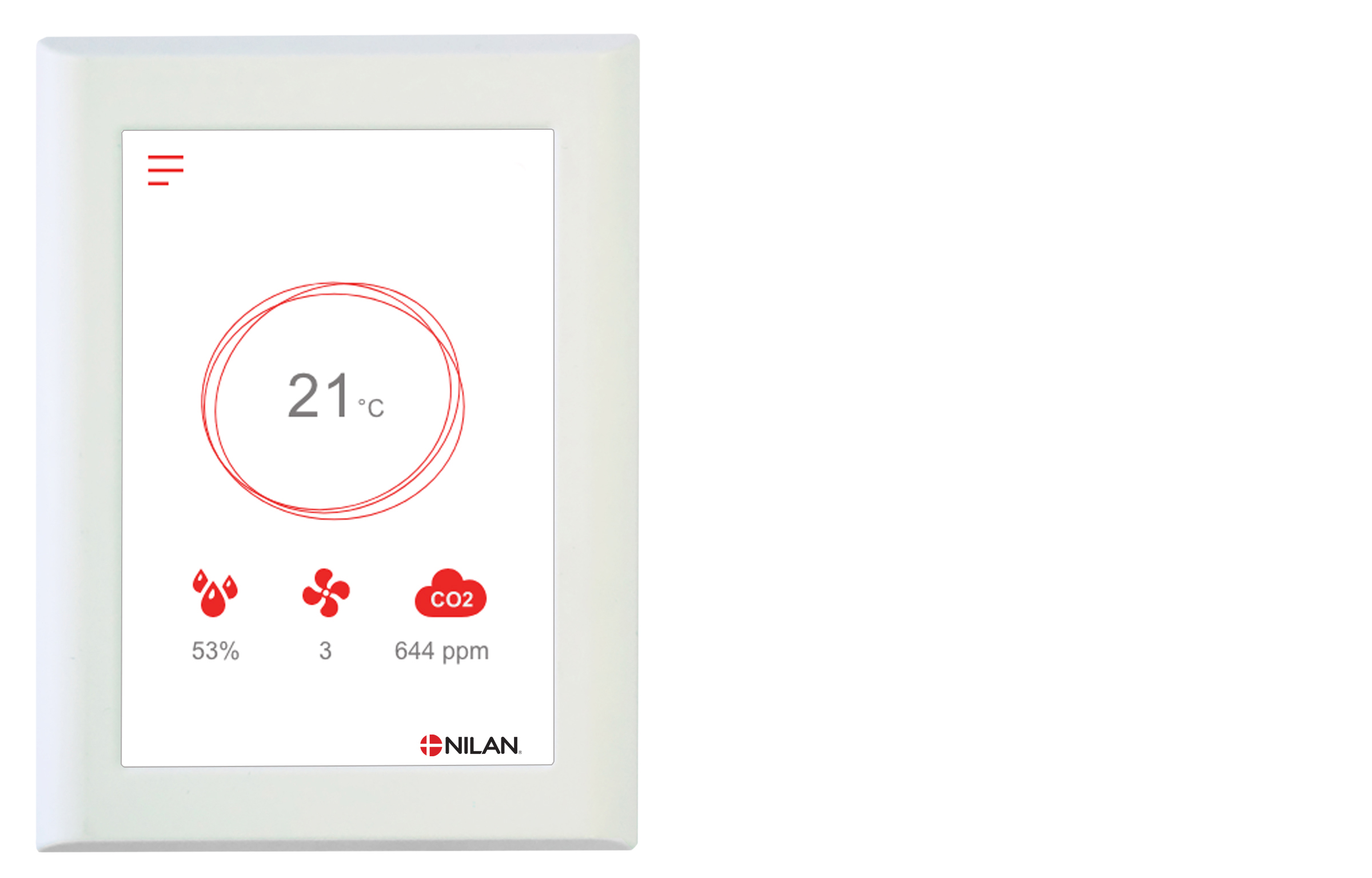
Nilan App - Control the ventilation and heat pump directly from the mobile phone
|
Nilan has developed a new App with great features where the user can control the ventilation and heat pump directly from the mobile phone. The App is intuitive, easy and safe to use, and allows the user to e.g. set the room temperature. More ventilation units can be connected using the same App to control the indoor climate in e.g. both the dwelling and the holiday home. More users can be connected the same App. When purchasing a Nilan gateway, the user can access the unit via the Nilan App. Get more information on the Nilan App
|
 |
|
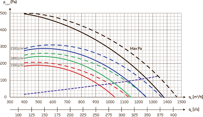
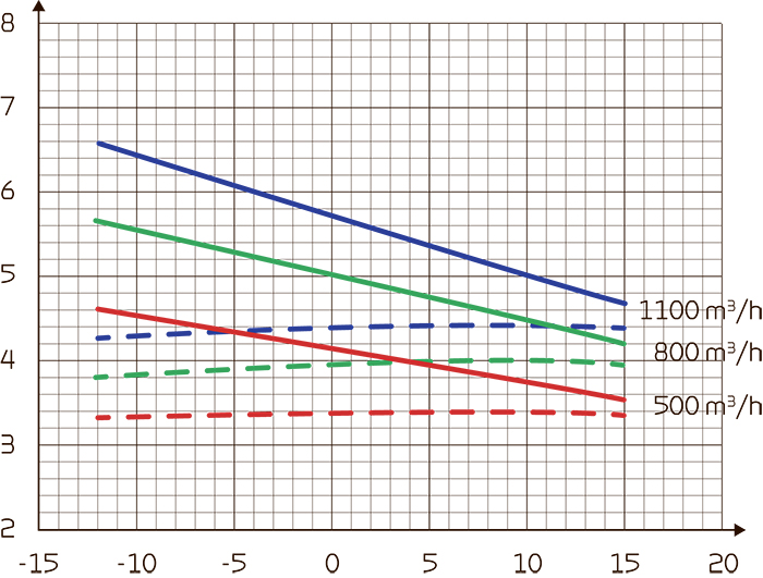
CapacityMax Pa capacity of standard unit, Pt,ext as a function of qv, with regard to SEL-values. SEL-values according to EN13414-7 for a standard unit with ISO ePM10 >50% (M5) and ISO ePM1 50-65% (F7) filters an no heating element. SEL values comprise the unit total power comsumption incl. control. Conversion factor: 3600 = W/m3/h. Attention! The SEL values are measured and stated as a total value for both fans. |
 |
COP (heating)Heat effect factor COP [-] supply air as function of outdoor temperature [°C] and volume flow qv [m3/h]. According to EN14511, extract air = 21°C. Dotted curve: Without FU15 heatpipe |
 |
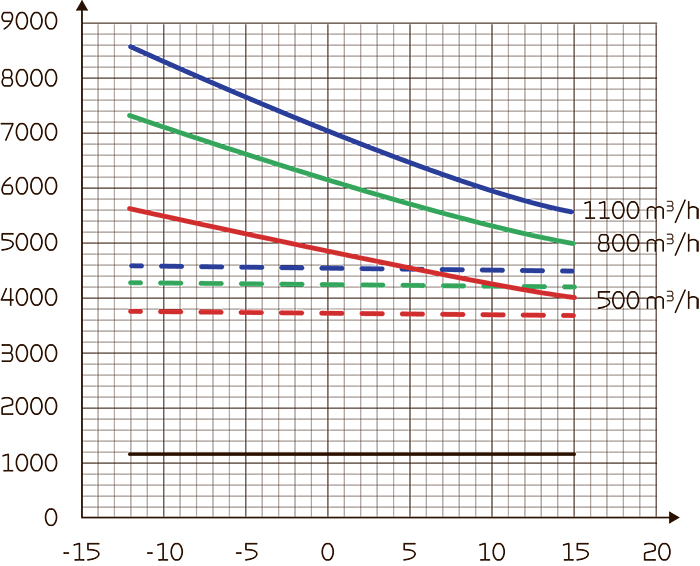
Heat effect (supply air)Heat effect Qc [W] as a function of qv [m3/h] and fresh air temperature [°C]. According to EN 14511, extract air = 21 °C Dotted curve: Without FU15 heatpipe |
 |
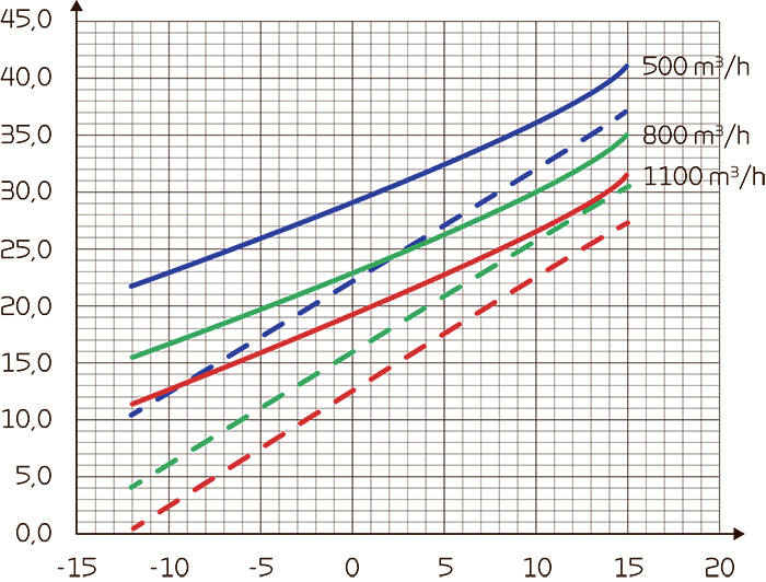
Supply air temperature (heating)Supply air temperature [°C] as a function of fresh air temperature [°C] and volume flow qv [m3/h] balanced flow. Extract air temperature = 21 [°C], 45 RH [%]
Dotted curve: Without FU15 heatpipe |
 |
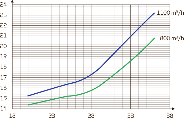
Supply air temperature (cooling)Supply air temperature [°C] as a function of fresh air temperature [°C] and volume flow qv [m3/h] balanced flow. Extract air temperature = 24°C |
 |
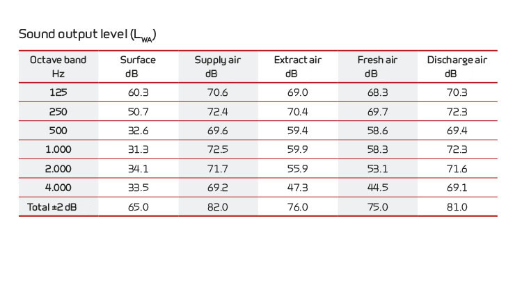
Sound dataSound data for qV = 1000 m3/h and Pt, ext = 200 Pa according to EN 9614-2 for surfaces and EN 5136 for ducts. Sound output level LWA drops with falling air volume and falling back pressure. Sound output level LpA at a given distance will depend on acoustic conditions in the place of installation. |
 |
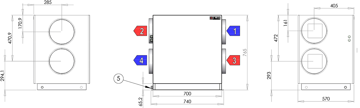
Dimensional drawing VPL 28:
All dimensions are in mm. Connections
|
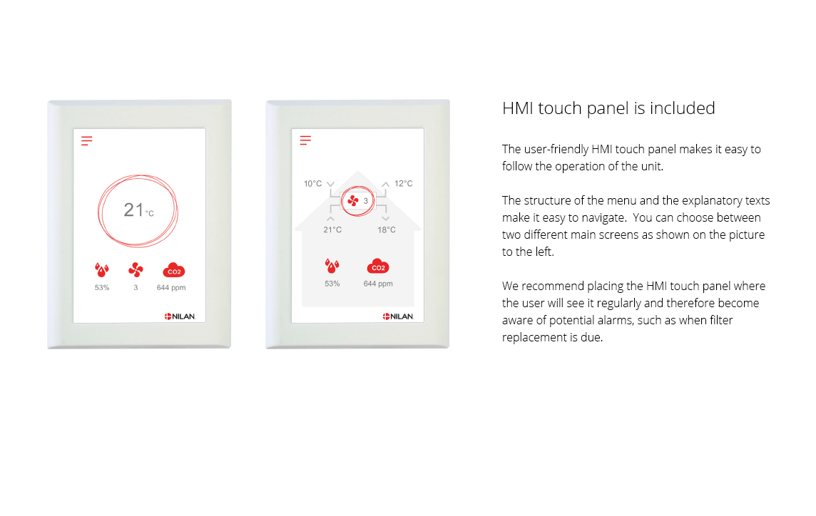
The CTS602 control system is an advanced control system with many settings options. The control system is supplied with factory default settings that can be adapted to the operational requirements in order to achieve best possible operation and utilisation of the unit. The HMI Touch panel provides an overview of the current operation of the unit, and the structure of its menu makes it easy to navigate for both user and installer. There is an option for selecting between 2 front page images for the main screen. External communication
You can find further information about all the functions in the Software and Installation instructions for the unit.
|
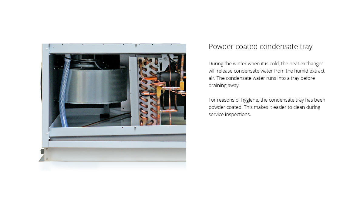
ATTENTION! When positioning the unit, you should always consider future services and maintenance. It is recommended that you leave a minimum of 60 cm of clear space in front of the unit. It must be easy to replace filters and it must be possible to replace, for instance, fans and other components. ATTENTION! The unit must be level to enable proper drainage from the condensate tray.
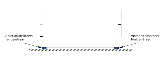
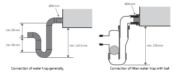
The unit makes little noise and produces only weak vibrations, but you should still take into account potential vibrations that can spread from the unit to individual building components. In order to separate the unit from its foundation, it is therefore recommended that you install vibration absorbers under the unit. There should be approx. 10 mm distance to other building components and to permanent fixtures. Condensate drainATTENTION! You MUST install a water trap in connection with the condensate drain to ensure that condensate water can drain away. If you set up the unit outside the climate screen, it is important to use a heating cable to prevent the condensate drain from icing up. Frost protection of the unit is the installer's responsibility.
|